
A commercial solar system is not purchased. It is financed. The investment thesis is a 25-year cash flow: energy cost savings and generation revenue against capital repayment, O&M expenditure, and the residual value of the asset at the end of the project term.
That framing changes what ‘good engineering’ means. A structure that meets code at commissioning but requires structural remediation in year eight has not failed a technical standard. It has failed the business case. The cost of remediation access, fabrication, installation, downtime does not appear in any compliance checklist. It appears in the project IRR.
At S.M.E.I. Renewables, we think about what a 25-year performance horizon actually demands from the engineering and installation. This article covers the variables that determine whether a commercial solar structure reaches its design life or falls short of it and what decisions, made early, have the most influence on that outcome.
Material Selection: The Decision That Cannot Be Revisited
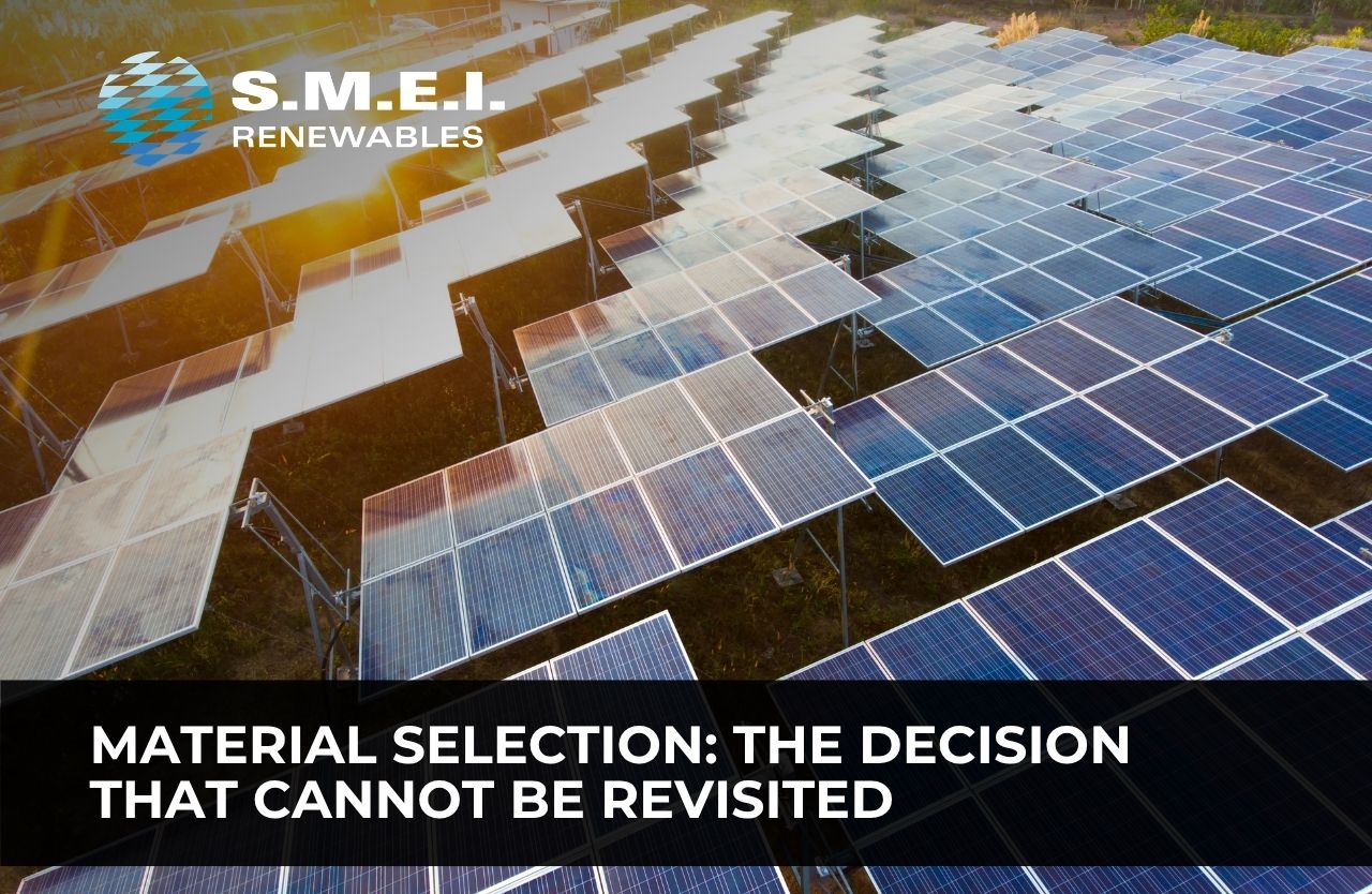
The structural steel in a commercial solar installation is inaccessible for the vast majority of its operating life. Embedded foundation sections are underground. Column bases are at ground level in a zone of high moisture cycling. Every bolted connection is exposed to the same environmental conditions as the surrounding steel. Once the structure is installed, the scope for corrective intervention is limited. The material selection made at the design stage is largely permanent.
Hot-dip galvanised steel, specified and applied to SANS 121:2011 (aligned with ISO 1461), is the correct base specification for the South African climate across the range of environments where commercial solar projects are developed. But specifying ‘hot-dip galvanised’ is the beginning of a corrosion protection decision, not the end of it.
The variables that determine whether a galvanised structure reaches 25 years without loss of section are:
- Coating thickness relative to the base steel section, verified at an accredited facility using calibrated electronic gauges.
- Site corrosion category, assessed against ISO 9223 classification criteria, accounting for proximity to marine environments, industrial emissions, and agricultural chemical use.
- Below-ground coating treatment, which requires separate specification from above-ground structural elements, standard zinc coatings are often insufficient for aggressive soils.
- Connection hardware specification, including bolt grade, coating compatibility, and long-term clamping force under repeated thermal cycling.
For sites in South Africa’s coastal zones the Western Cape, KwaZulu-Natal, and Eastern Cape coastlines, marine aerosol introduces chloride loading that accelerates zinc depletion at rates well above inland reference values. A structure designed using inland corrosion assumptions and installed in a coastal C4 or C5 environment will lose protective coating decades ahead of its design life. The remediation path from that outcome, typically abrasive blasting and recoating of in-situ structure, is expensive and disruptive.
Steel section selection also carries long-term consequences. Column wall thickness, weld quality, and connection plate sizing all influence fatigue behaviour under the repeated load cycles that accumulate over 25 years of wind, and thermal expansion. These decisions are made once. They need to be made correctly.
Designing for Extreme Weather: Beyond the Design Load Case
The load case that governs structural design, the maximum wind speed at the design return period, combined with the design dead and imposed loads is not the only loading condition a 25-year structure will experience. It is the condition the structure is explicitly designed to survive. The question that requires more nuanced engineering is how the structure behaves under sub-design loads experienced repeatedly over decades.
South Africa’s wind climate is more varied than early code editions assumed. SANS 10160-3:2019, updated following research at Stellenbosch University, raised the partial safety factor for wind loading from 1.3 to 1.6 to better reflect the country’s dual wind regime: convective gust fronts from summer thunderstorms across the interior, and extratropical cyclone events along the southern and western coasts. A solar structure that was designed to the pre-2019 code on a site in a wind acceleration corridor may have been compliant at installation and under-designed relative to the actual loading environment it will experience.
Thermal loading is a second mechanism that structural designs can underweight. Steel in South Africa’s Highveld and Northern Cape experiences daily temperature swings of 20 to 30 degrees Celsius across much of the year, and seasonal swings that extend well beyond that range. In a long-span solar carport differential thermal expansion generates cyclic stress at every fixed connection point. Over 25 years, this accumulates as fatigue.
The design response to thermal loading is not exotic: it requires correctly positioned expansion provisions, appropriately specified connection flexibility, and foundation details that allow controlled movement without progressive loosening of anchor bolts. These are not features that can be retrofitted without significant intervention. They belong in the original design.
Structural Inspection and Maintenance: What a 25-Year Programme Looks Like
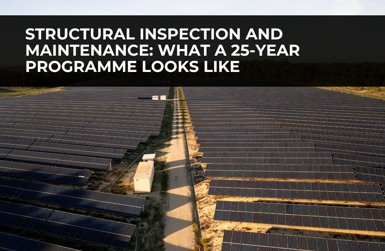
A commercial solar structure with no maintenance plan is not a low-maintenance asset. It is an unmaintained asset, and the distinction matters when the remediation cost eventually arrives.
A structured inspection and maintenance programme by a maintenance team for commercial solar structures typically includes:
- Annual visual inspection of all accessible structural connections, column bases, foundation collars, and purlins, with photographic record and comparison to baseline.
- Five-yearly detailed structural inspection by a qualified structural engineer, assessing corrosion progression, connection integrity, and structural movement against original as-built drawings.
- Torque verification of bolted connections on a schedule appropriate to the loading environment, typically every two to three years for high-wind exposure sites.
- Corrosion treatment of any damage to the galvanised surface identified during inspection, using compatible zinc-rich paint systems applied to prepared surfaces before the base steel is exposed.
- Foundation settlement monitoring for sites with expansive soil conditions or seismic activity, using reference datum points established at commissioning.
The South Africa Solar O&M Best Practice Guidelines, referenced in the industry’s broader performance framework, establish monitoring and inspection intervals as a baseline expectation for commercial solar assets. Lenders and insurers increasingly treat documented O&M programmes as a condition of project financing and coverage. An asset owner who cannot demonstrate a structured inspection history faces complications at the point of refinancing, sale, or insurance claim.
Vegetation management deserves specific mention. In ground-mounted and carport installations, uncontrolled vegetation growth beneath the array introduces shading losses, elevated fire risk, and moisture retention at column bases that accelerates corrosion. It is the simplest maintenance intervention and the one most commonly deferred until the consequences are visible.
System Upgrades Over the Operating Life
A 25-year solar investment does not operate with the same hardware at year 25 as it does at year one. Inverters, monitoring systems, and increasingly the modules themselves are replaced over the project lifecycle. The structure needs to have been designed with this reality in mind.
Inverter replacement is the most predictable intervention. Commercial string and central inverters carry typical operating lives of 10 to 15 years. A project financed for 25 years will replace its inverters at least once, and possibly twice. The structural and civil implications are straightforward if the original installation was designed around equipment replacement: adequate cable routing clearance, accessible enclosures, and conduit sizing that accommodates upgraded wiring specifications. They become costly if the original design was optimised for minimum material content without regard for what happens in year twelve.
Module technology has advanced considerably since the commercial bifacial formats that now dominate new installations were introduced. In the medium term, next-generation module formats with higher power density and altered physical dimensions will enter the replacement market. The ability to upgrade to higher-yield modules on existing racking depends on whether the structural design incorporated appropriate clearances, rail adjustability, and load margins for modules that may be heavier or carry greater wind area than the original specification.
Engineering Decisions That Determine the 25-Year Outcome
The decisions that most influence whether a commercial solar structure reaches its design life, corrosion protection specification, structural connection detailing, thermal expansion management, and O&M programme design, are almost all made during engineering. They are not visible in a commissioning report or a year-one performance summary. They accumulate their consequences slowly, in ways that are usually traceable to specific choices made before ground was broken.
That is the case for engaging an engineering partner who will still be available to answer questions in year ten. Not because anything will necessarily go wrong. But because when something does, the value of having the original design team, the as-built documentation, and the engineering rationale accessible is impossible to overstate.
S.M.E.I. Renewables designs and constructs commercial solar structures under ISO 9001, ISO 45001, and ISO 3834 certified quality systems. We retain full as-built documentation and structural design records for all completed projects. If you are developing or engineering a commercial or industrial solar project and want to discuss what lifecycle performance engineering actually requires, contact us to arrange a site-specific assessment.